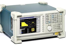
LEIS Overview
The VersaSCAN LEIS integrates the Base with a VersaSTAT 3F with Differential Auxiliary Option , an electrometer and a dual-element probe. The LEIS technique calculates local impedance by determining the ratio of AC voltage applied to the sample and local AC current measured at the probe in solution. LEIS adds spatial resolution to applications such as organic coatings, bare metal corrosion, and any application that benefits from the added information content of AC-techniques.
-
Compatible Potentiostats: VersaSTAT 3F with Differential Auxiliary Option
-
Capable of running both fixed-frequency /swept position plots for data maps and fixed-position / swept-frequency plots Bode or Nyquist plots
-
Capable of Time-Resolved Imaging when programmed as a sequence
-
Can perform Constant-Distance operation in conjunction with a topographic measurement technique, typically OSP.
The VersaSTAT 3F applies an AC voltage to the sample emerged in electrolyte. This "global" voltage generates AC current to flow at the electrode / electrolyte interface. A dual-element probe is positioned in solution close to the surface of the sample. The electrometer measures a differential voltage measure between the two measurement elements as a measure of local voltage-drop in solution. This voltage-drop exists in solution because of current flow from local reactions at the sample, the resistance of the electrolyte and the spatial separation of the dual measurement elements.
The VersaSCAN’s electrometer inputs its measured voltage to the Auxiliary Differential Voltage Input available with the VersaSTAT 3F.
Software integration converts the measured local voltage-drop at the probe to local AC current.
The ratio of local measured current to the global applied voltage gives the localized impedance magnitude and phase shift.
There are two different test methods for the experimentalist to use LEIS to evaluate their samples
A) Chart the local response of a sample from a range of applied AC frequencies in a single location. Data can be viewed in either a Bode or Nyquist representation.
B) Create a series of data maps to characterize an AC response as a function of probe position. Data can be used to create a map, using either Magnitude or Phase as the response.
LEIS Specifications
| Potentiostat (VersaSTAT 3F): | |
| Compliance Voltage | ±12V |
| Polarization Voltage | ±10V |
| Current Ranges & Resolution | 4nA to 650mA standard; 120fA on 4nA range |
| Differential Auxiliary Voltage Option: | Enabled |
| Input Voltage Range | ±10.0V |
| Input Impedance | 10k Ohm |
| Gains | X1, X5, X10, X50 |
| Low Pass Filters | 1Hz, 10Hz, 100Hz, 1.0kHz, 10kHz, 50kHz, 200kHz |
| Notch Filters | 50/100Hz, 60/120Hz |
| Bandwidth | ≥3MHz |
| ADC | 16 bits resolution, 2µs conversion rate |
| ADC Voltage Resolution | 305µV, X1 gain, 61µV, X5 gain 1, 30.5µV, X10 gain, 6.1µV, X50 gain |
| DC suppression | ±10.0V, 16 bits, 305µV resolution |
| Probes: | Dual element probe |
SKP Overview
The VersaSCAN SKP integrates the Base with a Signal Recovery Lock-in Amplifier, a piezo-based vibration module, an electrometer and a tungsten-wire probe. The SKP technique measures relative work function difference between the measurement probe and that position on the sample. This is a non-destructive technique typically ran in ambient or humidified air, absent of electrolyte. Relative Work Function has been demonstrated to be able to be correlated to Corrosion Potential (Ecorr). SKP adds spatial resolution to applications such as materials, semi-conductors, and corrosion of metals…even with coatings on them.
-
Compatible Lock-in Amplifier: Signal Recovery 7230
-
Capable of Topography Mode experiments to measure and set probe-to-sample distance
-
Can perform Constant-Distance operation in conjunction with the Topography Mode experiments, using the same probe.
The Kelvin Probe experiment uses a nondestructive method to determine the relative work function difference between the probe and the sample. Work function describes the energy required to liberate an electron from the surface of a conductor; electrochemists often interpret this as the difference from an electrode’s Fermi Level, average energy of electrons, and that of vacuum.
A metal microprobe is positioned close to the surface of the sample (on the order of 100-microns). If the microprobe and sample are of different metals, there is an energy difference between their electrons. The microprobe is then electrically shorted to the sample, through internal electronics of the system. As a consequence, one metal forms a positive charge on its surface and the other metal forms a negative charge on its surface. The probe and sample are separated by a dielectric (air), so a capacitor is formed. The probe is then vibrated and "backing potential" or "nulling potential" is then applied sufficient to minimize this capacitance. At the applied voltage that causes the capacitance to go to zero, the original state is achieved. This value is recorded and charted.
Experiments are typically performed in ambient gaseous conditions, but several published examples use humidified environments. The underlying conducting sample can have an organic coating or paint applied.
This relative work function can also be correlated to an Ecorr value.
Our SKP is also capable of functioning in Topography Mode. Without changing connections or probe, a reference voltage is applied to the sample. This reference voltage makes the surface of the sample uniform. Change in capacitance is then from a changing plate separation (via equation of a capacitor).
This information can be used in 2 ways:
Position the probe a known distance from the sample, using a Calibration Coefficient.
Map topography for further use in Constant-Distance Mode SKP. This is particularly useful in studying welds or other samples of complex topography.
SKP Specifications
| Lock-in Amplifier: | |
| Noise Sensitivity | 13fA per second |
| Frequency Range | 1mHz up to 250 kHz |
| Full Scale Sensitivity | from 10nV to 1V |
| DSP Stability | Impervious to temperature drift |
| High Mechanical Stability | No fan for failure |
| Piezo: | Up to 30-microns vibration perpendicular to sample surface |
| Electrometer: | |
| Gain | from 1x to 10,000x in decades |
| Probes: | |
| Material | Tungsten |
| Dimensions | 500-micron and 250-micron diameter probes are available |
| Backing Potential Controller: | |
| Range | ±10V |


