Overview
Analyzing low conductivity, low loss materials stretches the capabilities of even the best frequency response analyzers (FRAs). Used alone, they lack the sensitivity required for accurate measurements, especially at low frequencies.
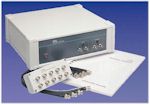
The 1296A Dielectric Interface overcomes these limitations to give you fast, accurate and repeatable impedance measurements over 12 decades of frequency, yielding valuable insights into the characteristics of a wide range of materials, including polymers, ceramics, ion conductors, dielectrics, piezo/ferroelectrics, display materials etc. Coupled with easy-to-use software, a 1296A-based system takes care of experimental technique and lets you concentrate on interpreting the results.
The 1296A enhances the capabilities of Solartron Analytical’s renowned 1260A and 1255A FRAs to cope with ultra-low current and capacitance levels experienced in testing dielectric materials, enabling:-
- Impedance measurements to exceed 100 TΩ (1014Ω)
- Accurate tan delta measurements down to <10-4
- Frequency range from 10 μHz up to 10 MHz
- AC signal and DC bias voltages up to 1000 V (with external psu or amplifier) revealing essential data in areas previously inaccessible.
Highly accurate reference capacitors are built in to 1296Afor sampling/reference testing, or you can choose to use an external reference, offering unrivalled flexibility to meet almost every measurement need. Support for temperature and DC controllers is integral to the measurement software, further increasing the scope for materials analysis.
Defining Dielectrics
Many materials have the properties of low conductance (high impedance) and low loss. They are often referred to as dielectrics, although many materials not normally considered as dielectrics exhibit these properties.
One popular technique for analyzing such materials is Impedance Spectroscopy – measuring the electrical impedance over a range of frequencies. The impedance is related to the conductivity and capacitance of the material, and these parameters can in turn be related to the molecular activity of the material.
When an alternating voltage is applied to a dielectric sample, some energy is stored by the capacitance, and some is dissipated by the resistance effects.
The resulting current in the sample will exhibit a phase lag, δ. In materials research, the capacitance effect is known as the permittivity (or dielectric constant) ε’, and the resistive effect as dielectric loss, ε”. Tan δ, the dissipation factor equals ε”/ε’.
In materials where ε” is very small and ε’ large, the resolution of tan δ becomes critical if an accurate measurement is to be made. The 1296A overcomes this by taking a reference measurement on a precision capacitor which is automatically substituted for the sample; a second measurement is made, this time on the sample itself. The two results are used to derive a very accurate estimate of the permittivity of the material – in effect, the first measurement is used to eliminate the effects of extraneous capacitance.
Temperature Options
- Model 1296010A Cryostat System covering 77 K to 500K, complete with solid and liquid sample holder for testing polymers, rubber, pharmaceuticals, etc.
- Furnace system covering 400-1000ºC, complete with sample holder for testing ceramics, composites, glasses etc.
- Room temperature sample holder for solids and liquids
Applications
The range of applications for a 1296A system is huge, and includes the investigation of:-
- Relaxation processes in the molecular dynamics of liquid crystals, polymers and liquids
- Charge transport in semiconductors, organic crystals, ceramics etc.
- Analysis of chemical reactions, polymerization and curing processes
- Non-linear electrical and optical effects
- Novel gas and liquid sensors
- Characterization of insulating and semiconductor materials
- Quality control in the production of insulators, printed circuit boards, etc.
- Fuel cell/battery materials
Specifications
| 1296+1260/1255 |
1296+1250 |
1296+1253 |
|
| Frequency Range | 10 µHz to 10 MHz | 10 µHz to 65 KHz | 1 mHz to 20 kHz |
| Signal Amplitude | up to 7 v rms* | up to 10 V rms | up to 10 v rms |
| DC Bias | up to ±40 V | up to ±10 V | up to ±10 V |
*For signals >3Vrms, an internal amplifier is used, and signal amplitude + DC bias must not exceed 10V peak
| Current measurement | 1 fA to 100 mA |
| Tan delta range | <10-4 to 103 (reference mode) |
| Impedance range | 100 Ω to > 100 TΩ (1014Ω) |
| Capacitance range | 1 pF to >0.1 F |
| Software | Provides control of FRA, 1296 and optional temperature controller, DC bias and AC signal amplifiers |
| Result parameters | Z*, Y*, ε*, C* (real, imaginary, magnitude, phase, tan δ) |
| plotted vs | frequency, time, temperature, bias, ac level |
| on | Bode, complex plane |
| Power supply | 85 VAC to 264 VAC (47 to 440 Hz) |
| Power consumption | 30VA max. |
| Dimensions (w x h x d) | 13.39" (340 mm) x 4.72" (120 mm) x 11.81" (300 mm) |
| Weight | 12.13lb (5.5kg) |
| Operating temp. range | 10 to 30ºC (50 to 80ºF) |


