FEATURES
- High-speed (up to 100 MS/s), High Resolution (up to 16-bit), Isolated (up to 1kV*1)
- Multi-channel, up to 128 Voltage/Temperature or 128 logic bits
- Continuous hard disk recording at 100 kS/s simultaneously on 16 channels*2
- CAN and LIN buses monitoring and trend waveform display (DL850V only)
- 17 plug-in modules
*1. With the isolated probe (700929 or 701947)
*2. With the /HD0 or /HD1 option
The DL850 ScopeCorder Series are modular, waveform recording instruments that can measure voltage, current, strain, acceleration, and other phenomena– simultaneously. With high speed sampling, high isolation withstand voltage, and multichannel measurements, the DL850 Series offers powerful support in the development, evaluation, and quality control of energy efficient devices.
High speed (100 MS/s), High resolution (12-bit), 1kV isolated measurements.*
Yokogawa's isoPRO technology offers industry-leading isolation performance at the highest speeds. The isoPRO core technology is designed with energy savings applications in mind. It gives you the performance needed to develop high efficiency inverters, which employ high voltages, large currents, and high operating speeds.
Example – Measuring Inverter Output
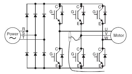 Accurately observe inverter startup waveforms with sufficient time resolution. You can confirm that no excessive overshoots occured.
 |
High Speed & High Withstand Voltage Isolation Technology | |
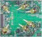 |
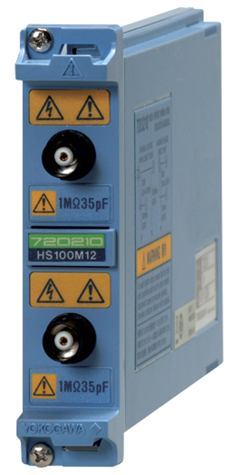
Using high speed optical fiber-based transmissions, the module achieves high speed ADC clock and data isolation. 720210 High-speed 100 MS/s 12-Bit Isolation Module(Max. four(4) modules can be installed in a main unit.) |
 |
|
Rising waveform not completely captured
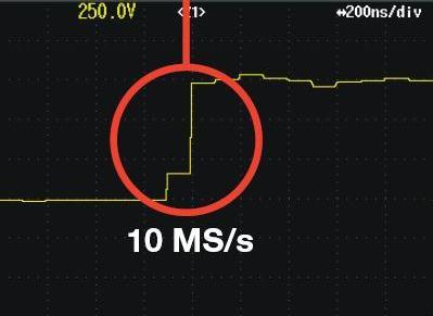 |
Rising waveform accurately captured
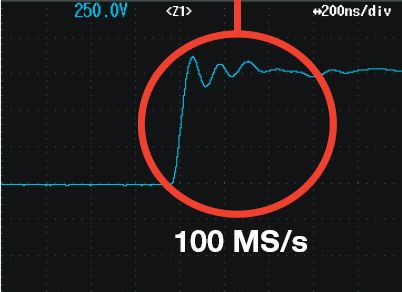 |
Example: Same inverter output waveform measured at 10MS/s and 100 MS/s
The lineup includes two new module types: A 16-CH Temp./Voltage Input Module, and a CAN & LIN Bus Monitor Module (DL850V only). All DL850 modules can be combined with measurement modules from the DL750 series products:

|
|
Note: The firmware version 2.00 or later is required when using the 16-CH Temp./Voltage Input Module(720221) and/or CAN&LIN Bus Monitor Module(720241).
The 16-CH Voltage Input Module (scanner type*) can measure at 10 kS/s sample rate even when using all 16 channels. With this module populating all 8 input module slots, the DL850 performs 128-CH voltage measurements.
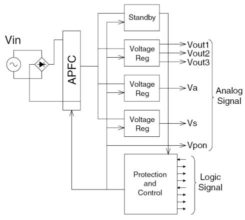
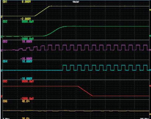
Power supplies used in home computing electronics have many outputs, and it is necessary to control the sequences from output to output. With a multichannel module, you are not limited to voltage measurements; a single unit can also measure everything from PC control signals to AC fan operation, individual component temperatures, and slow to high-speed signals.
 |
Ch 1: AC Input Voltage Ch 6: Supply Voltage Ch 2: Reference Voltage Ch 3: Reset Signal Ch 1: Fan Rotation 16-bit logic: Control Signals 4-bit logic: Serial Communication
|
 |
To visualize long term trends in durability testing and other situations, data is typically acquired at low-speed sample rates. On the other hand, suddenly-occurring transitional phenomena should be captured at high-speed sample rates.
The "Dual Capture" feature resolves these conflicting requirements by recording at two different sampling rates.
-
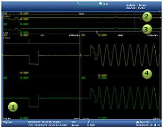
Zoom Waveform – You can record up to 5,000 phenomena of high speed trigger measurements (up to 100 MS/s) at a record length of 5-500 kPoints while taking trend measurements at up to 100 kS/s.
- Event Waveform -Displays the timing at which high speed "sub" waveforms are acquired
- Low Speed Main Waveform – Max: 100 kS/s Trend waveform displayed in a low-speed Roll mode
- Capture Waveform – Max 100 MS/s Capture transients with high speed trigger measurement
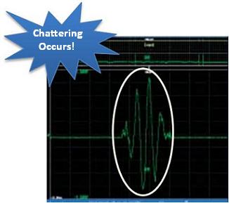
Example: Parts Durability Testing
- Chattering is accurately captured at high-speed sampling
- Check the frequency of occurence at low-speed sampling
FU NTIONS
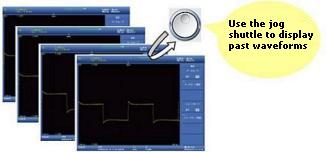 To extract abnormal waveforms
|
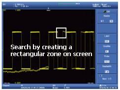 |
When you want to extract abnormal phenomena exclusively, you can perform condition-based searches of the history waveforms. You can create a rectangular zone on screen and extract only waveforms that pass through or do not pass through the zone. You can also extract data based on amplitude and other parameters.
To check the history…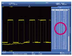 |
You can display all past waveforms, and view a list of acquisition times at min 1µs resolution |
| Key Point The History function requires no action during measurement. You can recall data at any time after measurement has been completed. Once waveforms have been recalled, you can zoom locations of interest or perform parameter measurements. |

- Edge: Trigger on a single trigger source condition (rising, falling, rising/falling)
- Time: Trigger at a specified time or fixed interval
Enchanced
- A -> B(N): Trigger when condition B is true N times after condition A becomes true
- A Delay B: After condition A becomes true, trigger the first time condition B becomes true after a set time has passed
- Edge On A: Trigger on an OR condition of an edge trigger while the A trigger is true.
- OR: Trigger if at least one trigger condition of multiple trigger sources is true
- AND: Trigger if all trigger conditions of multiple trigger sources are true
- Period: Trigger when a condition regarding the waveform period becomes true
- Pulse Width: Trigger on a condition relating a pulse width condition being true with a specified time width condition.
- Wave Window: Trigger when the signal passes outside of an real time template "Wave Window"
Example: "A Delay B" trigger setup screen (GUI)
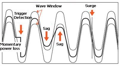 *The Wave Window is not displayed on the display.
|
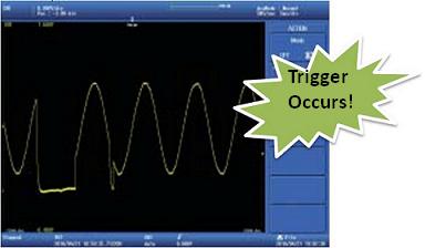 |
You can specify "e-mail transmission" for immediate notification in a remote location when a phenomenon occurs. |
|
 Excellent noise rejection performance is achieved through meticulous low-noise design. Floating voltage switching waveforms in inverter circuits can also be captured with precision.
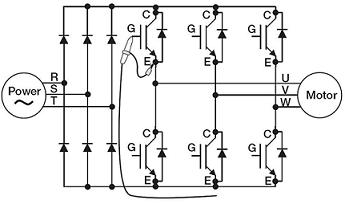 |
Example: Measuring inverter gate signals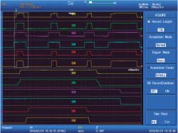 |
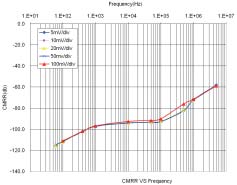 Model 701250 Voltage Input Module
|



![Pressure Transmitter Workshop Re-range – [HART 475 / Fluke 789 / Druck DPI610 / Foxborough TX]](https://www.calibrator.vn/wp-content/uploads/2021/06/L7T92J7wpzE-218x150.jpg?v=1625029240)



Comments are closed.